Part 2
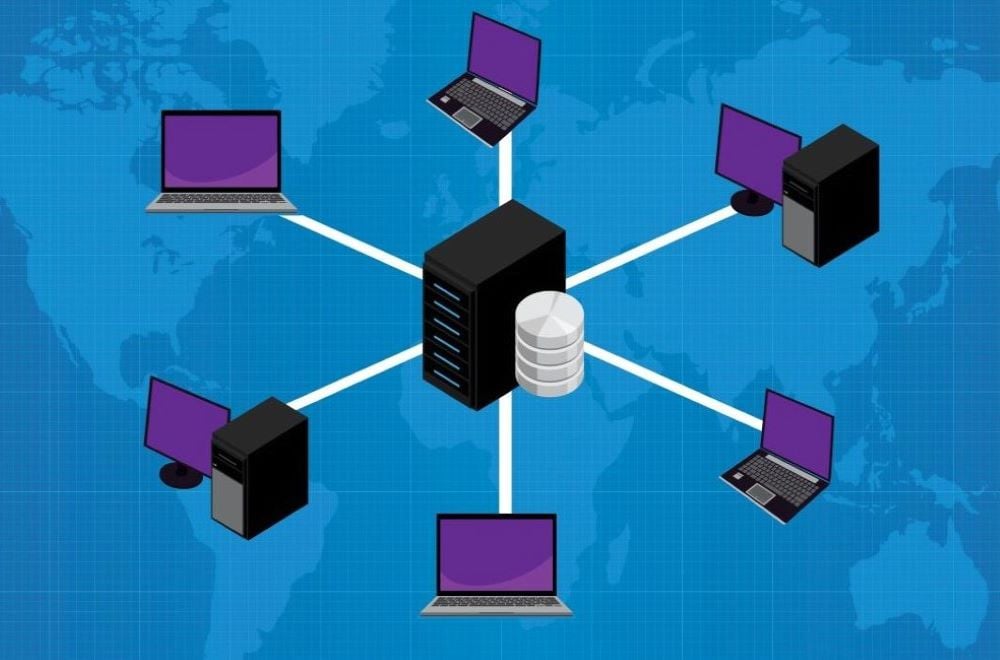
A SCADA network connects all of the devices at a solar PV site. It not only allows the SCADA server to communicate with the field devices, but it allows the networked devices to communicate with each other.
This is the second of three articles in our series on SCADA networks. The first covered SCADA network equipment. Let's move on to local SCADA networks and devices.
What is some of the typical network equipment that would be found in a substation?
Typical equipment includes switches (either managed or unmanaged), firewalls and routers. (See Part 1 of this series for a refresher on these devices.) Servers and production servers are also part of the network, but are considered computers, not network-specific devices.
What are some of the common issues that can be found with this equipment?
Issues can include hardware failures (i.e. a bad cable, port, or internal processor failure) or software failures (i.e. firmware failure or bad configuration). Common misconfiguration issues include incorrect IP addresses, subnet mask or gateway.
What are some of the common solutions to these issues?
The solution to these issues depends on where the problem originates. Issues with networking equipment can originate from four different layers:
- Application layer: Allows the user to interact with the application. This layer handles high-level protocols, including HTTP, HTTPS, RDP, SSH, etc.
- Transport layer: Responsible for flow control, reliability and correction of data. This layer defines what kind of connection needs to be made, like TCP or UDP.
- Internet layer: This layer is responsible for sending data packets. It assigns IP addresses for the traffic source and destination. Routers operate at this level.
- Network access layer: Also known as the physical layer. Responsible for transmitting data between devices on the same network. This layer deals with Ethernet protocol and defines how data should be sent physically through the network. Network switches operate at this level.
We will cover these layers in more depth in Part 3 of this series, when we discuss TCP/IP and troubleshooting. For now, let us look briefly at how the layers can help identify network equipment problems and solutions.
For example, let's say you have a device that isn't visible on the SCADA server (not sending any data for example). How can you narrow down the many possible causes so you can resolve the issue? Here is a typical troubleshooting scenario:
1. You start at the Internet layer by "pinging" the device to see if it is accessible. If the ping returns a successful ping, you can confirm the device is still on the network but not communicating with SCADA.
2. If the ping is not successful, you know there is no connectivity. Next, you try pinging other devices. The other devices are pingable. You now know that there's not a larger problem (such as a loop issue) and you can continue your investigation of the one device. This can involve pinging the device from other computers, from the firewall (Gateway), or even from a different port in the firewall (other Gateways), trying to isolate the connectivity issue. Let us say that none of the pinging is successful.
3. You can go down a layer to the physical/network access layer. This involves physically inspecting the cable, connections, power, ports and hardware to make sure they are good. If they are not, the solution may be as simple as tightening a connection. You may need to repair or replace a cord, port or hardware. For this example, though, let's say that the connections are good. You now know the problem with the device isn't physical.
4. You've now investigated the bottom layer (network access/physical) so there's nowhere to go but up. You can go back up to the Internet layer to investigate what IP address has been assigned to the device during configuration. There may be some network mask misconfiguration, wrong Gateway or even a mistyped/duplicated IP address on the device's interface.
5. Let's say that you discover the Gateway address is off by one digit. This is surprisingly common, especially with inverters and on the network loops. One number throws everything off. Resolving this issue involves correcting the number; sometimes the device must then be power cycled to get it back online. This issue is caused by human error—often a simple copy-paste or transposition mistake. The solution is to have a system for double-checking the numbers during the configuration process.
This process of using layers to narrow down and identify network problems will vary depending on the nature of the issue. You begin with the layer you think will be the best way to test and confirm the failure. Troubleshooting ability grows with experience, training and familiarity with the system.
What are some common SCADA protocols used in networks?
A protocol is a system of rules that allow two or more entities in a network to communicate. The sender and receiver of the information must agree on the protocol.
Modbus and DNP3 are two of the most common protocols used in SCADA networks. Modbus is open source, and 80-90% of plant devices (inverters, trackers, etc.) "speak" Modbus protocol. DNP3 is a newer protocol that is primarily used to communicate between different substation devices in the SCADA system.
At Nor-Cal, we typically recommend DNP3 for critical devices like substation devices, and Modbus for the remainder of the devices in a plant.
What is a VLAN and how is it used in a SCADA network?
VLAN stands for Virtual Local Area Network. You'll remember from Part 1 that switches are used to connect all of the devices on a Local Area Network (LAN) so they can communicate. All of the devices on a LAN are part of the same network.
Think of these devices on a LAN as people sitting in the same conference room. Let's say there are 20 of them. They can talk to one another without going outside the room. They are locally connected. They are close. They use a switch to communicate.
Now, let's say that 10 of these people are in the business development department and 10 are engineers. They're part of the same company, but on different teams. They need to have private discussions within their own teams, but everybody in the room is talking at the same time and it's confusing. The teams can overhear each other.
That's what happens with devices on a switch that are part of the same LAN. They "hear" one another (in the case of broadcast messages). In some cases, this may be what you want on your network. What do you do, though, if you need to separate or segregate the traffic so only certain "teams" of devices hear it or have the ability to communicate directly (locally)? What if you need more privacy and better control over the traffic within or between networks?
Before VLAN technology, the only way to segregate traffic was to use two different switches. With the creation of VLAN, you can assign specific access numbers or VLAN numbers to different ports on the same switch. This gives each "team" its own separate way to communicate without the need for more switches. It is like creating a smaller switch within a switch. Devices on a VLAN only communicate with devices in the same VLAN, making these communications more secure. If the devices do need to communicate outside of the VLAN, this would require a router.
Security is the biggest advantage of using VLANs. Flexibility is another. If you need to add more devices to a "team" or add an entirely new "team," you can do so without having to get a new switch or change the cabling. All you have to do is change the settings on the existing switch. You have the flexibility to divide ports within the switch to create new Virtual LANs.
Another advantage of VLANs is a restriction on network traffic. Traditional network broadcasts can cause an overloaded network. The bigger the network, the more broadcast messages go out, which occupies more bandwidth. That's not beneficial. With VLANs, you have fewer devices on the network, which limits the amount of the broadcast.
What are the different Common Network Diagrams?
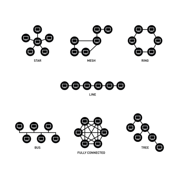
Fully Connected Network Topology
A fully connected network is obviously the most reliable, but most solar PV sites don't go this route due to the huge cable cost.
Mesh Network Topology
A full mesh network offers high redundancy and reliability, but is also cost-prohibitive. Adding a device to the network requires the addition of a lot of cabling. It isn’t easily expandable. For these reasons, it isn't common to see an entire system on a full mesh, though it may be used for certain core or distribution sections of the network that require redundancy. A half mesh topology is much more common.
Star Network Topology
This is a common network topology used in solar PV sites. It offers fast performance with few nodes. Each node has its own dedicated connection. However, if the hub (the center switch) fails, the whole network fails (single point of failure).
In order to add redundancy, the star can be built out with two switches and two firewalls. The cabling between the switch and firewall and server should be full mesh. There should be multiple paths to these key devices should one fail.
Ring Network Topology
This network topology is easy to handle and is the cheapest way of having redundancy. The transmitting network is not affected by high traffic or by adding more nodes. However, failure of more than one device in the loop (ring), could possibly cause network partial loss.
Ring networks are commonly used on solar PV sites, but only for loops. You can read more about loops in our SCADA System Architecture article.
Common Bus Topology
This topology was developed before switches were invented and is no longer used for solar PV SCADA systems.
Learn More About SCADA Networks
This is the end of Part 2 of our article series on SCADA networks. Learn more in Part 3, covering TCP/IP and troubleshooting.
If you are a solar industry professional who wants to learn more about SCADA networking, we invite you to attend our quarterly Solar PV Operations Training sessions. SCADA networks are covered in-depth on Day 2 of the 3-day training. The training is system agnostic, meaning it can be applied to any SCADA system platform. We hope you join us!